Engineering and Design
Olivia Velten-Lomelin
Portfolio

About Me.
My name is Olivia Velten-Lomelín and I am a first-year Master's student at Stanford University studying Mechanical Engineering in Robotics. I graduated from MIT in June of 2025 with a Bachelor's in Science in Mechanical Engineering. My interests lies in robotic applications to improve our oceans and environment using novel systems such as soft robotics and bio-inspired mechanisms.
In addition to the core curriculum of my degree, my studies have primarily been focused on control design and its applications. However, my professional experience in labs and internships has mostly involved mechanical design, materials research, and small-scale manufacturing.
Welcome to my portfolio--please feel free to contact me with any questions or comments.

Engineering


The Product Engineering Process - Neptune
2024
Last fall, I was enrolled in The Product Engineering Process—an MIT mechanical engineering capstone—working to launch an underwater communication device for Scuba divers. I was voted by my peers to co-lead our team of 18 and was one of three team members who presented our product in front of a live audience of over a thousand people. Our device allows scuba divers to communicate to one another by pressing buttons that correspond to specific messages. Nearby divers then receive their signal in the form of an auditory message through bone conducting headphones.
In addition to my role as a team lead, I led the mechanical subteam, reviewing all mechanical aspects of the product throughout production and led a 3D modeling workshop for my team on Autodesk Fusion. I designed and tested all of the waterproofing of the system and the button housing with which the user interfaces. The housings were simulated on Fusion under pressure and tested in a flooded pressure chamber to 500kPa--equivalent to around 40 meters of water depth. All mechanical parts of the assembly were SLA printed or CNC machined. Lastly, I was responsible for all team branding. Our product brochure can be found here.


Fleet Robotics - Robot Test Stand
2024
Fleet Robotics is a Somerville-based start-up developing ship haul inspection and cleaning robots to reduce fuel emissions and the spread of invasive species. During the summer of 2024, I worked as a Mechanical Engineering Intern.
Along with other projects, I designed and built a robot test stand that could hold the robot in various orientations. The test stand only requires one person to shift the robot between its positions. It includes an automatic mechanical locking system that prevents the robot from sliding on the linear rails it is mounted to. Gas springs are used to counter the weight of the robot when bringing it to its vertical position. I manufactured the test stand using t-slotted framing that I cut to size using a miter saw and constructed using custom-made PAHT-CF brackets I designed. All designs we made using Fusion 360 and parts were printed with both FDM and SLA 3D printing.


Fleet Robotics - Compliance Research and Design
2024
Fleet Robotics is a Somerville-based start-up developing ship haul inspection and cleaning robots to reduce fuel emissions and the spread of invasive species. During the summer of 2024, I worked as a Mechanical Engineering Intern.
My work was focused on modeling and designing compliant mechanisms for the robot to withstand obstacle collisions. This included analytical Matlab models on the current mechanism, research on different fabrication methods such as heat treatment and SLA resin printing, and new design concepts. After modeling the current mechanisms, I tested them using two tests that I designed that simulated different scenarios the robot could find itself in--the first being sweeping over an obstacle and the next traversing curved surfaces. Testing revealed subtle points of failure we had been overlooking, redirecting my work from strictly compliance to designing protective mechanisms.
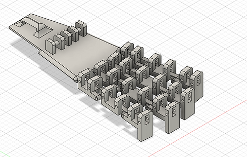
At the end of my research and design process, I designed a new passively adapting guardrail system that protected exposed components from collision damage. The guardrail was split into six sections for ease of assembly. Each section comprised two passively moving ramps meant for collisions incoming from opposite directions. Each ramp fits into the base with dovetail features to reduce the use of fasteners. Not shown in the image for security purposes are the components the guardrail is meant to protect. I presented my work along with other projects I worked on during the summer to the team including the CEO and founder.
The images below are images of the guardrail along with other test fixtures and components I designed.


Measurement and Instrumentation - Final Project
2024
For my final project for MIT's 2.671--Measurement and Instrumentation--I explored acoustic sensing in long filament soft robots for contact sensing. This project was a small portion of a larger project Professor Becker and I have been leading at the Fabrication-Integrated Design Lab since August 2023.
Acoustic contact sensing entails detecting changes in the frequency and amplitude of sound signals transmitted through a silicone filament using a speaker and received by a microphone at the opposite end of the filament while a force sensor taps the filament at its center. Analysis of Fast Fourier Transforms (FFTs) of sound samples demonstrated a proportional relationship between low-frequency response and peak contact force magnitude, allowing contact force magnitude to be predicted using acoustic sensing.
Findings were documented in a ten-page research paper and presented during a final poster session for the course.


Bio-Inspired Robotics - Final Project
2023
As a final project for Bio-Inspired Robotics--a course taught by Professor Sangbae Kim--my team and I were tasked with modeling a biological process to uncover new information that cannot necessarily be derived through mathematics analysis alone. We decided to model a Volleyball spike to relate wrist stiffness to maximum ball velocity achieved. This mechanism had two degrees of freedom--the rotation of the elbow joint and the rotation of the wrist joint--both powered by a motor. To model our mechanism, we used Lagrangian Dynamics to derive the equations of motion and used MATLAB to derive the forward kinematics of the system. To specifically model the wrist stiffness we implemented an effective stiffness on the wrist motor using a PID controller. The forearm joint also had implemented a PID controller. The idea was that as the forearm swung, the inertia of the hand would cause the hand to whip due to the implemented stiffness. We simulated and tested our mechanism using MATLAB and Mbed.
Our simulation found no clear correlation between wrist stiffness and ball velocity--contrary to our initial hypothesis. Our experiment showed that the ball velocity increased then remained constant after an effective stiffness of k=3N/m. We presented our findings and mechanism to our section and the broader MIT community. If more time would have allowed, we would have investigated the timing of wrist stiffness implementation and its correlation to maximum ball velocity.
The mechanism was completely custom made using Fusion 360. Parts were machined both using a Waterjet and FDM 3D printer. The system used a belt and belt tensioning system to drive the rotation of the hand to reduce the rotational inertia of the system by locating the hand motor at the base.


Boston Dynamics - Large Part Organizational Racks
2023
During summer of 2023, I worked as a Manufacturing engineering intern at Boston Dynamics. In addition to resolving production blockers such as instruction ambiguity, defective parts, etc., I designed, built, and implemented three organizational racks for the large components of Stretch--a case handling factory robot. These racks are mobile and are now being used daily in the assembly line. The overall design process included choosing the racks, fasteners, protective matts and foam, and struts along with ordering all of these components and tracking their inventory.
Each rack holds 23 different components in the order that they are used in the work instructions on the main line. I met with the technicians that work on the main line to get their suggestions and preferences for how they wanted the racks to be set up. This included differently sized components on different levels, descriptive labels including graphics of the orientation of each component, etc. Each rack takes about 12 hours to build up if all materials are available and I created work instructions for how to build up the racks. The racks are currently being used at Boston Dynamics.


Boston Dynamics - Thermal Paste Applicator
2023
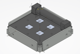
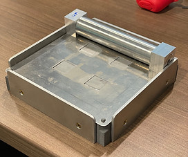
During summer of 2023, I worked as a Manufacturing engineering intern at Boston Dynamics. In addition to resolving production blockers such as instruction ambiguity, defective parts, etc., I designed, prototyped, and implemented a thermal paste application tool to be used in the assembly line of Stretch--a factory case handling robot. This tool applied thermal paste evenly on four LEDs on a 19.0mm X 19.0mm +/- 1.0mm area at a thickness of 0.3mm +/- 0.1mm. The assembly was designed on Catia CAD software and built using the following methods: HP Multi Jet Fusion 3D printing, CNC Mill, Lathe, Waterjet, and Laser cutting. The tool was made to speed up this step in the production process and make the thickness and application of the thermal paste consistent between different builds--regardless of what technician was using the tool.
I presented my project in a 15min presentation to the rest of the companies interns, recruiters, team members, and executives. This method is currently being used at Boston Dynamics.




Design and Manufacturing I - Final Project
2023
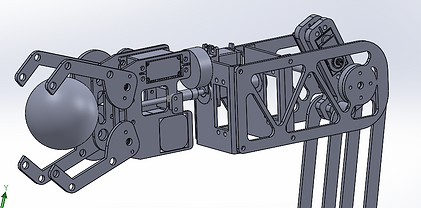
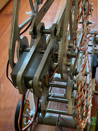
For the final project of MIT's Design and Manufacturing I class, we were tasked with building a robot to complete a series of tasks on a game-board to compete against the robot of another classmate. I designed, machined, and assembled a robot with a liftable actuated gripper. This gripper has six degrees of freedom (x, y, z, roll, pitch, and yaw). The system uses the gripper to pick up balls to be placed on a rotating platform four feet in height. The gripper also spins a wheel continuously as ~ 25rpm and can be used to perform more tasks on the game-board. The robot is machined out of aluminum, steel, and acrylic using a CNC mill and lathe, water jet, and laser cutter.
Since the gripper spins continuously relative to the rest of the system, it is fully controlled by a separate system since the wires of the servo that actuates the gripping cannot be lead back to the rest of the assembly without tangling the wires.


MIT Sea Grant - Mechanical Engineering
2023
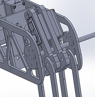
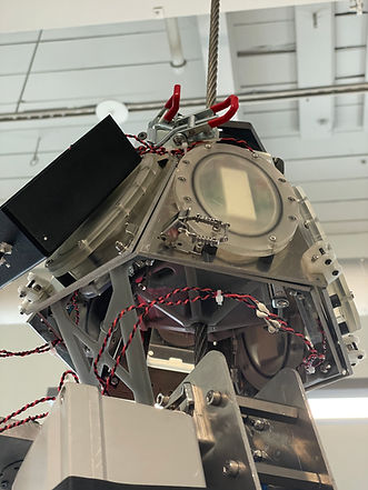
MIT Sea Grant is a Lab focusing on oceanic research, exploration, and engineering. With projects ranging from soft robotics, to underwater vessels, to automated boats, the lab is conducting research that is first of its kind. The project I am working on is an underwater zip-line robot that can be used to collect underwater measurements--'Zippy' for short.
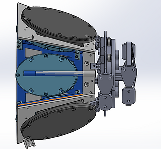
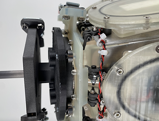
Currently, my primary focus on the project is an autonomous charging and docking system. Using wireless inductive charging, we are charging the robot with six wireless transmitters housed on the docking system. Mounted on the robot is the counter part charging system made up of six wireless receivers. Once the robot is nearing the end of its battery, it climbs back up the zip-line and mates with the docking system, charging the robot. All components on the system are waterproof and saltwater safe. Since the cable that the robot travels on can be in any orientation (straight or at an angle), the dock must stay in line with the cable regardless of it the cables orientation and external factors such as wind. However, the dock must be able to rotate on the cable axis and expand, allowing the receiver counter part to passively slide flushed into the system. Additionally, this entire system must be easily removable from the cable.


AttentivU - MIT Media Lab - Mechanical Design
2022
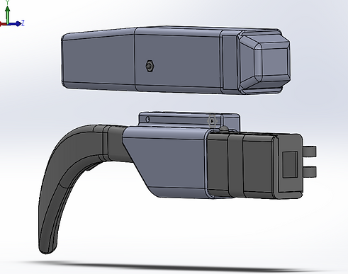
During the fall of 2022, I worked at AttentivU, a lab at the MIT Media Lab developing a pair of glasses that senses brain EEG activity and eye EOG movement to measure cognitive processes. The device is used for passive and active interventions, monitoring the state of a user and providing haptic feedback in response to low levels of attention from the user.
During my internship position, I designed and built a spring loaded sensor connected to one of the legs of the glasses. The part was designed to be adjustable for various head sizes, providing pressure from the spring metal onto the users head. This was to ensure that the sensor had adequate contact with the head to maximize signal measurements. The sensor can be turned on and off and be connected to a device by removing the sliding lid off the assembly, making it so that the sensor only needs to be removed when switching out the battery.
Moreover, I am worked on implementing laser cut lenses to the glasses and magnetic wire connectors at the hinges of the glasses to eliminate wires running through the hinges. These wires were previously subject to wear and tear as the pair is repeatedly opened and closed. These magnetic connectors will not only prevent this from happening, but it will also make it so the battery and the PCB board are not connected when the glasses are folded--minimizing battery usage.

BIOMEC Lab - Mechanical Design
2022
During the summer of 2022, I worked at BIOMEC, a biomechanics lab at UPC in Barcelona, as part of an MIT program that I was accepted into that sends students aboard, hosted by labs and companies all over the world. This lab focused on lower limb exoskeletons for stroke survivors.
The first of the projects that I was tasked with was a battery and PCB board housing that was mounted to the waist attachment of the exoskeleton. This included four different components: the PCB cover, the battery encasing, a sliding door, and a screwed door. The battery was removable and connected to a switch that turned on the PCB board. All parts were designed using Solidworks and printed in PLA. Moreover, I developed a battery charger for the smart RRC battery since the company had no yet released the charger. I did so using a battery charging chip from Analog Devices and GUI software.
Second, I designed and built an attachment method from the thigh to the hip that offered vertical support to the exoskeleton while allowing free leg movement. I did so using ball bearings for seamless rotation of the leg and an adjustable Click Medical boa attachment for side to side movement.
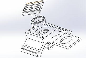
For the lower shank attachment of the exoskeleton, we were facing issues with user comfortability regarding the previously static nature of the design. To solve this problem, I installed a bearing into the design so that the attachment could freely rotate as the users leg moved.
This part is designed to be as compact and lightweight as possible. For this reason the part includes a sliding door to secure the bearing in place instead of screws. The design went through three different iterations, changing the way the bearing itself was secured. This final design secures the bearing through pressure forces instead of press-fits or friction.


Humidity Control of Smart Robotic Home Cleaner
2021
During my summer 2021 internship at Matician--a robotics start-up developing autonomous home cleaners--I was given the task to reduce the humidity levels inside of the bin of the robot. The vacuum motor inside of the robot was rated to run at 85% Relative Humidity; however, with the robots bin closed and the waste bag full of water, 85% RH is reached in under five minutes--damaging the vacuum motor.
I explored six different methods to reduce the humidity, ranging from passive mechanical solutions, to absorbent material based solutions, to actuated mechanical solutions. The two main concepts I focused on were absorbing water vapor using Silica Gel and sealing the bin with a flexible membrane. The membrane would be nominally open when the vacuum was not running--allowing air flow into the bin--but would suction onto the lid, sealing the bin, when running the vacuum. I ran dozens of tests on each of these concepts, taking internal and external humidity, temperature, and pressure readings. At the end of my project, I compiled all of my data and designs into a presentation that I presented to my team.


Robotic Hand
2020
For my capstone project of my engineering class in my Senior year of High School, I designed a user-controlled robotic hand. The system is broken up into two parts: a sensory glove worn by the user and the robotic hand.
The sensory glove was designed to comply with the stretching of a users hand as it opened and closed. The system uses an array of stretch sensors which measure the flexing and extending of a users fingers. The feedback of the sensors are then translated into servo inputs used by the prosthetic hand. According to the amount that a finger bends, the servo on the prosthetic pulls on a wire which in turn bends the 3D printed finger the same amount. All parts were created using Autodesk CAD and Fusion 360 and was coded using Arduino C++.
The design of the hand mimics the true biology of a human hand. In a natural hand, the muscles that move each finger are located not in the hand itself, but in the forearm. Likewise, in this design the servos that move the hand are located in the forearm of the prosthetic and wires attached to the servos pull on the tips of each finger to bend each finger. Elastic bands are located on the backside of the fingers to allow them to return to the extended position after bending. Unfortunately, due to Covid-19, I was unable to complete the next phase of the project which was to send sensory information back to the user in the form of electric pulses triggered by touch sensors on the prosthetic hand.



Brushless Electric Motor
2019
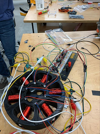
As part of my Applied Science Engineering class in high school, I built a brushless electric motor using six electromagnets that I made and an array of hall chips housed in a single 3D printed part. When one of the four permanent magnets on the internal spinning part rotates past a hall chip located on the inside of the motor, it triggers the preceding electromagnet switch polarity to repel that magnet, causing the magnet to rotate away from the e-mag. Simultaneously, the approaching electromagnet relative to the spinning permanent magnet is triggered to switch polarities to pull the magnet. Per each revolution, the motor switches 16 times, completing 4 cycles of the electromagnet configuration the motor. The configurations are combinations of the polarity of the electromagnets. This motor rotates at a top speed of 10,500 revolutions per minute. The motor was designed on Autodesk CAD and then FDM 3D printed. The circuit of the motor is controlled by six hall chips and a switching circuit using both npn and pnp transistors. A pair of hall chips change the polarity of two electromagnets making it so the complete circuit of the motor is three identical circuits of the circuit seen below--totaling to 18 transistors.


Weather Balloon Launch
2019
For a class project, I along with four of my peers designed and built a payload that was attached to a weather balloon. We each had a role our professor assigned us--I was team leader and balloon tracking. Throughout the building process we tested the payload to be able to withstand the extreme temperature and pressure of the atmosphere and incorporated heating mechanisms to prevent the Arduino from crashing and our batteries from draining. The balloon was launched and reached the atmosphere. The payload took measurements of pressure, temperature, radiation, carbon dioxide, acceleration as a function of air density, temperature in the wake of the balloon, and wind speeds in the stratosphere. Once the balloon reached a certain height, a collection of capacitors were triggered to send current to a wire to burn through a string attaching the payload to the balloon, releasing the parachute. For a month, my team and I worked after school and on weekends to ensure that all aspects of the project are working as a single unit. This was a semester long project which we launched out of Palo Alto, CA. The balloon landed in an unreachable cliff so we were unable to retrieve our data. We wrote a 100 page report, illustrating our findings and design process.


Design
Welded Chair
2019
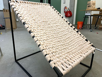
The final Project for my Design and Architecture class was to build and design anything that encompassed the concepts we learned in class. My objective was to build a chair that strayed as far as possible from a stereotypical design and create something that was adaptable to all. I settled with a combination of a minimalistic modern aesthetic with a shabby chic one. Moreover, I decided that I was going to make this chair out of metal tubing; therefore, I needed to teach myself how to weld and grind metal.
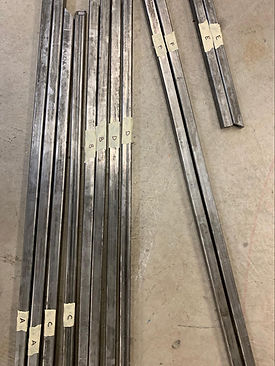
I first designed the chair on CAD software in order to determine the thickness of the metal I needed to use for the chair to be able to withstand a certain amount of weight. Once I had the design done, I cut and welded approximately 30 feet of steel rectangular tubing to make the skeleton of the chair and finished by weaving yarn to make a hammock like seat. The cutting, welding, and grinding process took over 20 hours in addition to the time it took for me to learn the skill. The weaving took another 4 hours.

Hex Lamp
2022
As a personal at-home project after finishing my first semester at MIT, I designed and built a lamp in my garage. Going into this project, I knew I would build it out of wood as I had most of the power tools needed to do so. Moreover, I wanted to challenge myself by cutting unconventional cuts without using fastened saws such as a miter saw or table saw in order to strengthen my wood-shopping skills. Using a hand held electric circular saw, I cut the five wooden pieces of the lamp, hand sanded them, and glued them together. I then stained the wood to give it a darker color and filled the gaps between the cuts with wood filler. I finished the lamp with a side made out of paper to offer a reflective glow and did the wiring of the light socket.


Poetry Lamp
2020
As a personal project my senior year of high school, I designed and built a lamp inspired by an independent study in poetry and creative writing. I wanted to find a way to combine two of my passions that are conventionally thought of as separate.
This is where I came up with the idea to have pages from a poetry book illuminated by light to see the overlapping of the different poems on each paper. I selected poems with the theme of light and suspended them from fishing wire stringing from one end of the lamp to the other. The acrylic encasing of the lamp is laser cut and the light bulb screw housing is wooden, cut by a bandsaw and electric sander.
"Source"
2019
As part of a project for a Design class, I designed and built a lamp. I set out with the goal of exaggerating the concept of light itself by using an 8 in x 12 in vintage incandescent light bulb and designing a frame that mimics the direction of the light.
To design the frame I began by sketching the pans out on graph paper, then transferring them to Autodesk CAD in order to make sure that the angles of each piece of wood were correct. For the actual frame, using a table saw, band saw, miter saw, and electric sander, I cut out six identical pieces of wood to construct hexagonal pyramid. The bulb itself is suspended using laser cut pieces of wood.

Graphic Design
Graphic Design - humanID
2020 - 2021
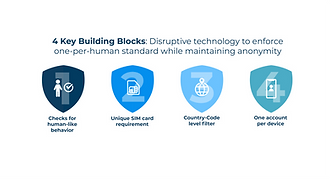
During the first six months of my gap year, I worked at humanID, a cybersecurity non profit start-up that provided apps and websites with a single sign on service to eliminate fake news, bots, and other threats. I began my work as a graphic designer for the content marketing team. I designed info graphics, icons, banners, logos, and the branding guidelines of the company. My largest project while working as a graphic designer was redesigning the company's website.
Two months into my internship, I was promoted to Marketing Team Lead. I was in charge of a team of eight people, ranging from graphic designers, to writers, to coders. I managed projects, proof-read articles, edited graphics, and met weekly with the company's founder.




Personal Projects
